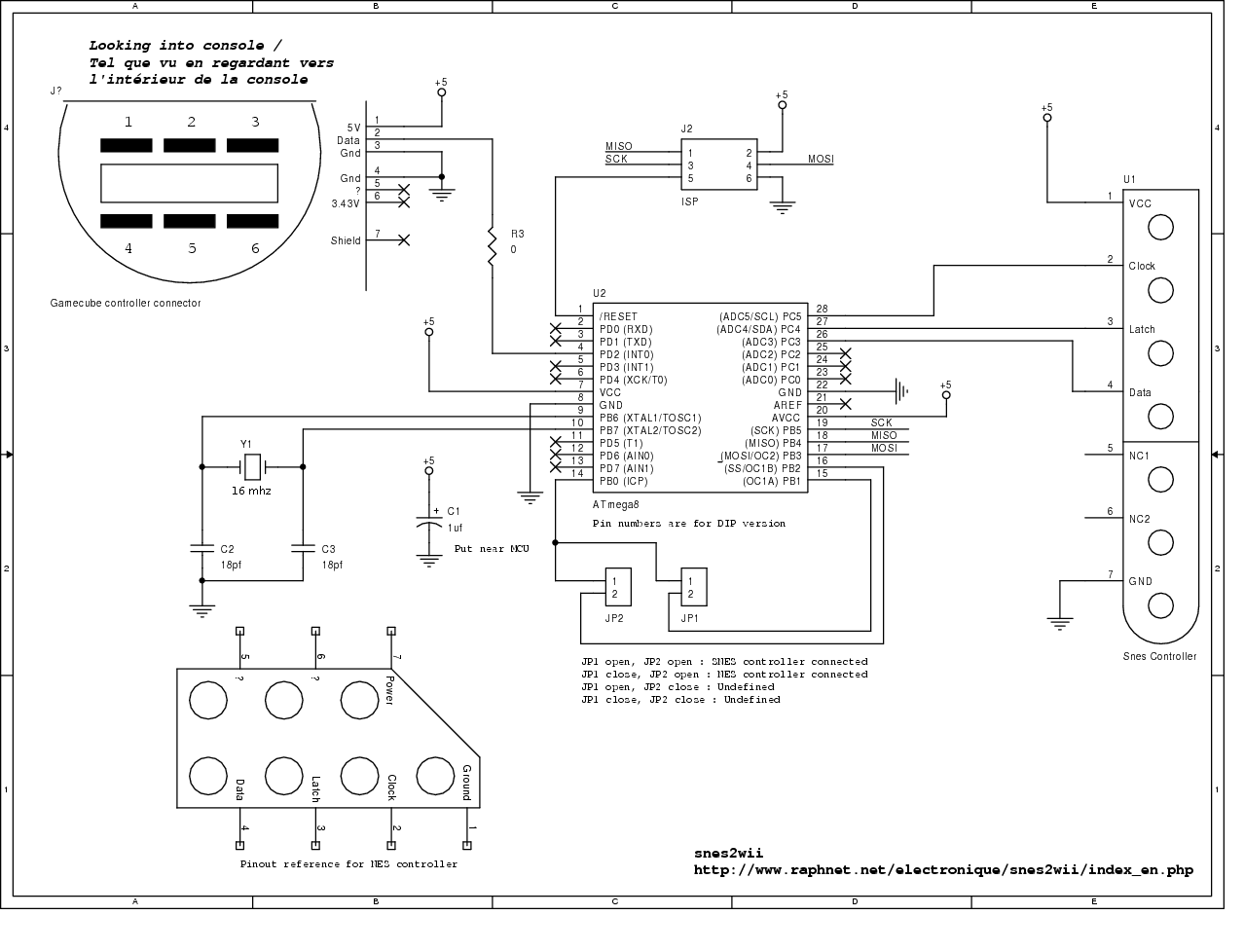
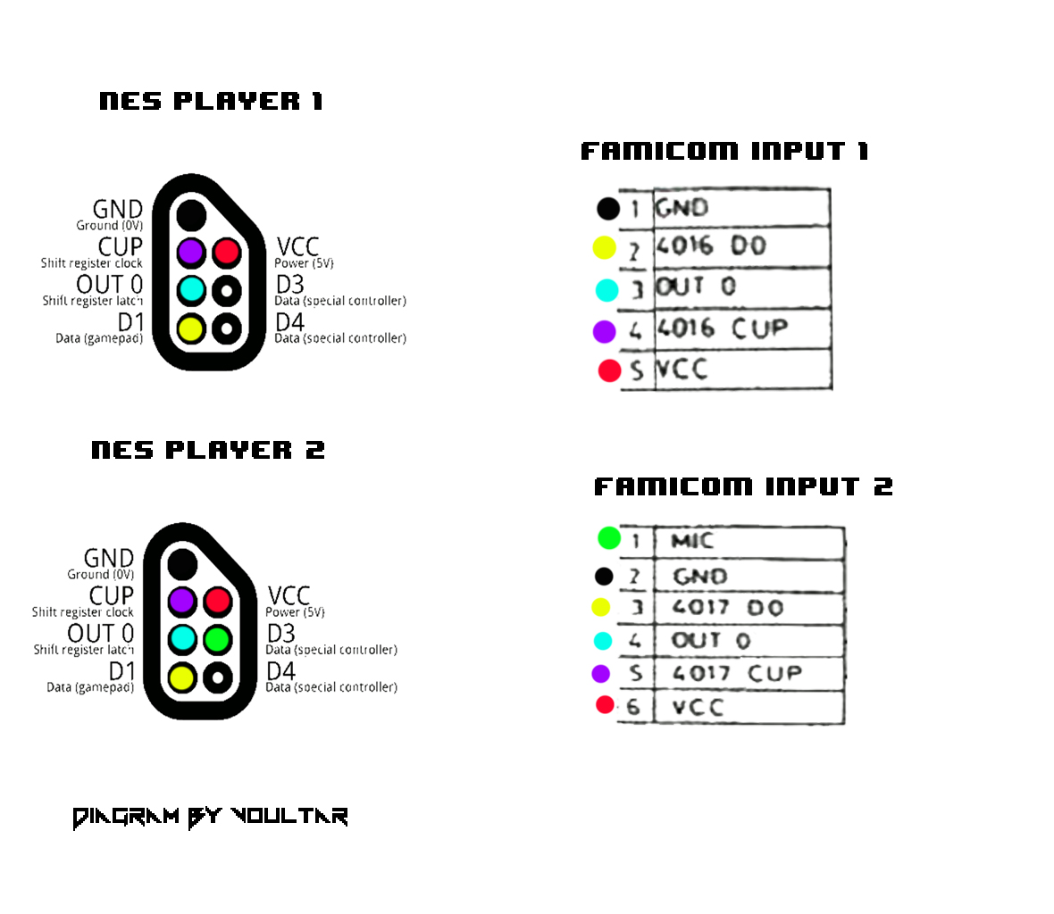
Nes Controller Wiring Diagram

Honda Xr200 Wiring Diagram, Skygo150 Voltage Regulator for XR200/Actual Wiring/Honda XR200 Modified/Supermoto/DIY Garage PH, 10.03 MB, 07:18, 10,383, D I Y Garage PH, 2021-01-23T08:48:03.000000Z, 19, Iam looking for a 1982 honda xr200 wiring diagram, www.justanswer.com, 904 x 703, jpeg, wiring diagram 1982 honda xr200 xt200 yamaha manual iam motorcycle looking 1981 mechanic bikee wire, 20, honda-xr200-wiring-diagram, Anime Arts
Snes multitap support (4 players) starting with firmware 1. 3, the snes multitap is supported. With this peripheral, 4 controllers are read using only 2 inputs thanks to a muliplexer controlled by a select signal. After latching the 4 controllers button states simultaneously using the 'latch' line, controllers 1 and 2 are read serially. The snes controllers drive data for the first button at the falling edge of latch.
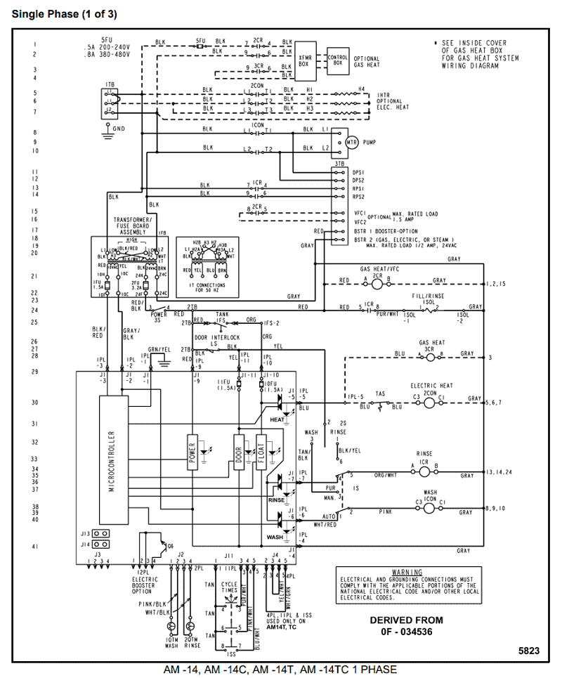
Hopefully the following timing diagram will serve to illustrate this. Only 4 of the 16 clock cycles are shown for brevity. This was designed to use with accessories such as the light zapper. I thought the schematic was a bit confusing myself, which took me longer to get the build complete. To properly read a electrical wiring diagram, one provides to find out how typically the components inside the system operate. For example , when a module is usually powered up also it sends out a signal of half the voltage and the technician will not know this, he would think he has a challenge, as he or she would expect a new 12v signal. Learn to solder correctly and use the right controller for the chip. This is where almost all problems occur. The retrokit is only designed for one controller.
Nes Controller Wiring Diagram

Nes Controller Wiring Diagram

Nes Controller Wiring Diagram

Nes Controller Wiring Diagram
Nes Controller Wiring Diagram
The Poor Student Hobbyist: Wireless NES Controller Using Arduino

The Poor Student Hobbyist: Wireless NES Controller Using Arduino

Nes Controller Wiring Diagram

Nes Controller On The Raspberry Pi | Gordons Projects with regard to Nes Controller Wiring
